LESSON OVERVIEW
What you're going to learn in this lesson, how you're going to do it and what you're going to get out of it.
INTRODUCTION
For this lesson, we will be discussing the basics of subdivision modelling, topology, and its importance within the game art pipeline.Over the course of the lesson, we should be able to grasp the concept of edge flow, the importance of support loops, and what defines good and bad topology.
LESSON OVERVIEW
WHAT IS SUBDIVISION MODELLING?
Subdivision Modeling (commonly known as Sub-d) is the technique of taking an object with simplified topology and subdividing it to increase its resolution.
To subdivide means to use an operation in your modeling software to divide the existing simplified mesh to create a smoother and denser surface. This terminology can be dependent on the program you’re using, but the common names for it are “Subdivide, Smooth, Turbosmooth, and Opensubdiv”
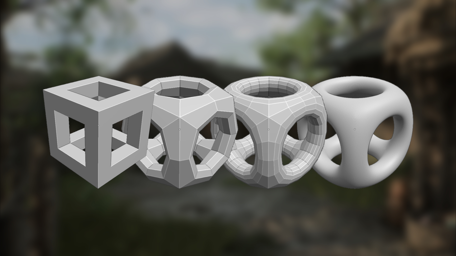
This is typically used in the game art pipeline to create a high poly mesh to bake down to and is frequently seen in a lot of hard-surface work involving weapons and vehicles. Sub-d is commonly characterized visually by having topology spread evenly all throughout the model in moderate to high resolution (subdivision levels) and featuring practices involving the use of support loops and edge redirection.
The clean nature of sub–d makes it ideal for this kind of work as it emphasizes the importance of highlights on large reflective surfaces, and the transition from smooth and curved surfaces to sharp ones seamlessly. It is also work that can be iterated on easily as you would primarily be working with a simpler mesh, then swapping between subdivided view and unsubdivided view often.
HOW DO I START MODELING WITH SUBDIVISION?
To model with subdivision, it’s important that we’re able to understand the basic concepts that are foundational to the workflow. These are overall very simple but are important to understand so we would be better able to use them for all kinds of models.
For this part, we’ll be tackling
- support loops
- edge distribution
- edge flow
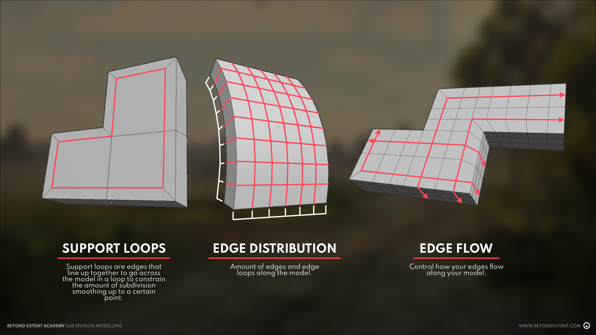
SUPPORT LOOPS
Support loops are edges that line up together to go across the model in a loop to constrain the amount of subdivision smoothing up to a certain point. Not to be confused with edge rings which are edges that are not directly connected together but share the same faces in between.
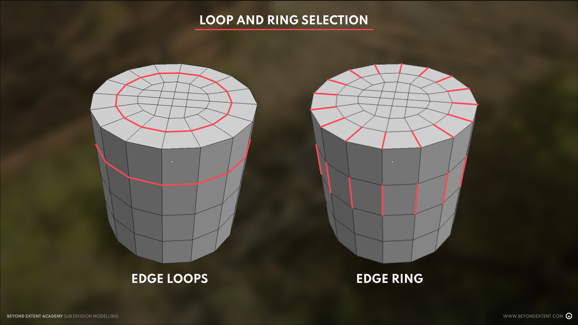
With this, we can control the amount of tightness the loop holds, and the amount of reflectivity and curve that the surface highlights.
These are typically placed by the edge of the outline of our model, which helps it retain its original shape. This can be easily achieved with an inward extrude, added edge loop or inset.
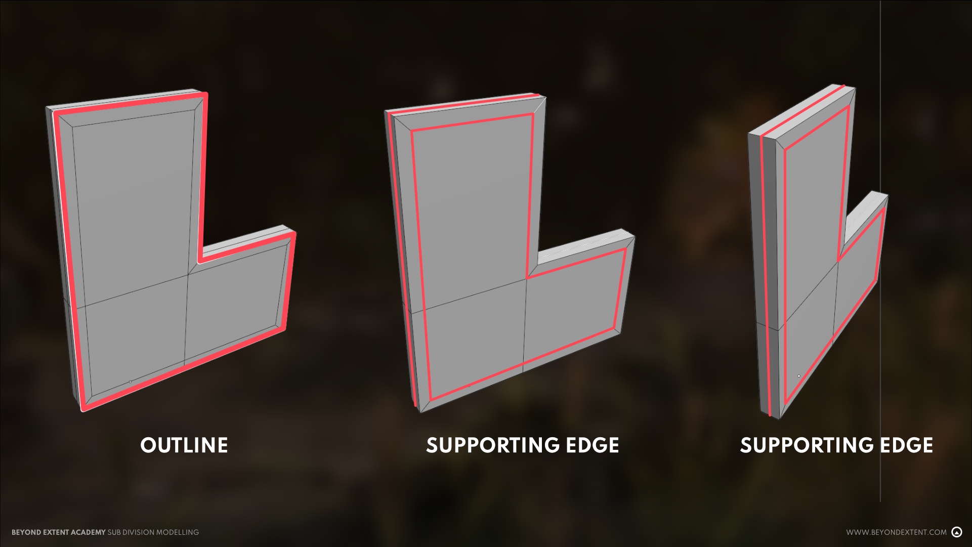
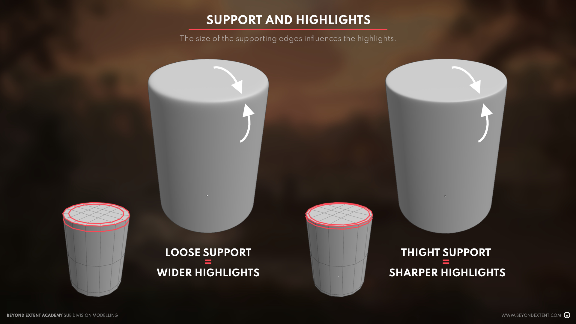
Support loops are the prime factor that influence the reflectivity and highlight of the edges after subdivision. A looser support loop creates a more rounded curve, creating a larger area to reflect light, while a tighter support loop creates a very sharp edge that reflects less light.
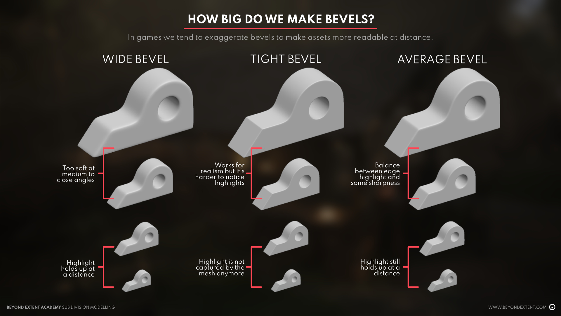
In real life, most objects that qualify under hard-surface tend to be machine made and milled to a certain accuracy. These make real life bevels and curves to be quite tight. But in games, the preference is to make these curves and edges to be looser and more reflective. This allows light in the engine to bounce off and make the model look much better in player view. Keep this in mind for your work and know what your goals are with regards to how much reflectivity you want your models to have.
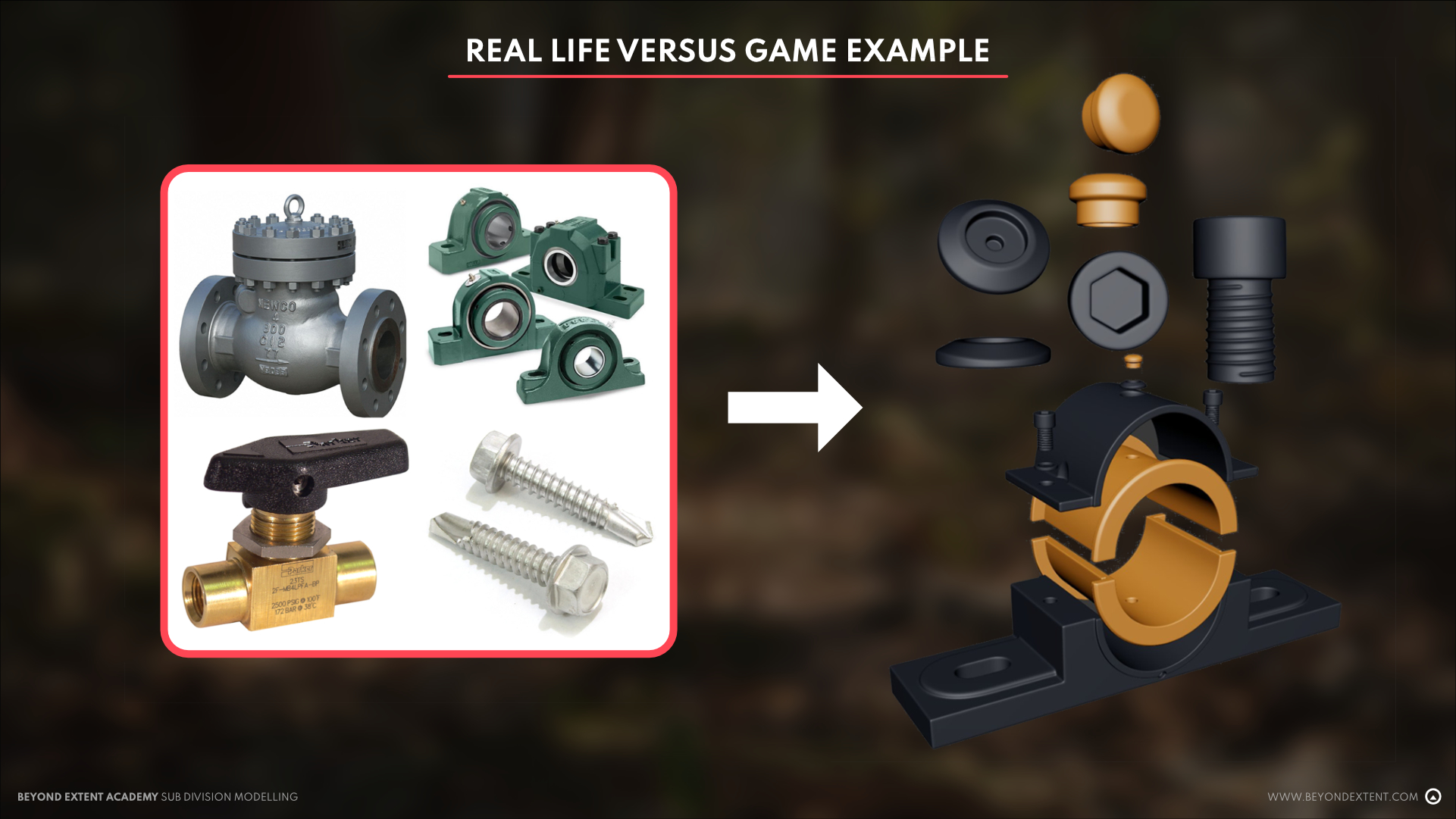
Below, you can see some examples of how edges are created in real life as opposed to how they would likely be interpreted in games. This all depends on what camera angle they’ll be seen from so take notes from the example above and determine how much edge sharpness you need for your use case.
<aside>🔥 (additional hard-surface breakdowns: 1, 2, 3, 4)
</aside>
EDGE DISTRIBUTION
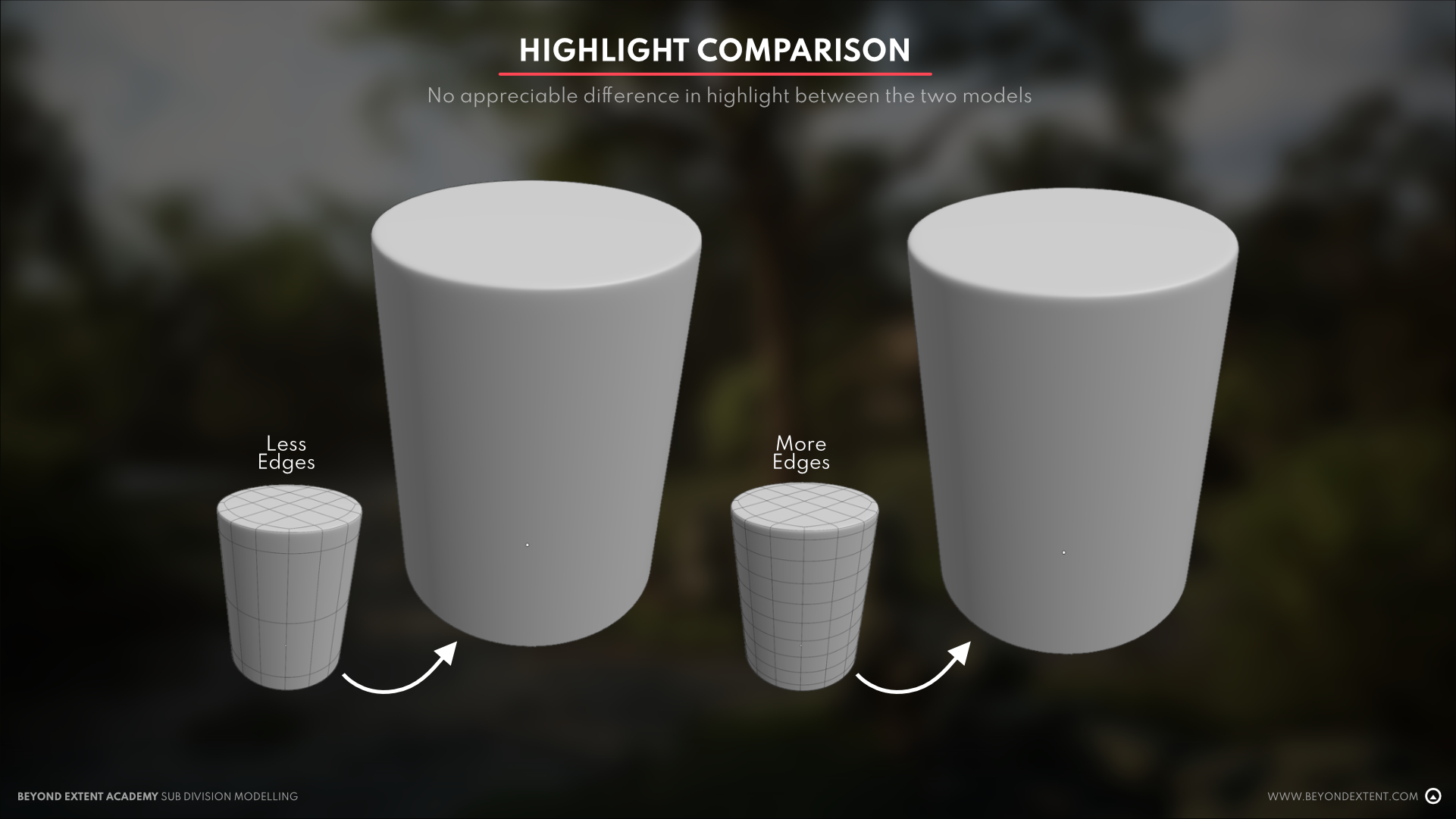
Edge Distribution, also known as Edge Density, refers to the amount of edges and edge loops along the model. Like support loops, these add more constraint where they’re placed.
With sub-d modeling, it’s preferred to have an even amount of edge distribution across the model so that shading remains uniform all throughout. This also allows the model to be modified in cases where a surface would need to be bent or skewed. This even amount of topology allows there to be little to no distortion with regards to the highlights and the overall shape of the model.
To know whether you have good distribution or not, an easy and simple way to tell would be to check if the inner edges created are more or less perfect squares. Next, you preview it with subdivision depending on your program of choice. In Maya, this can be viewed by switching between 1 and 3 on your keyboard, in 3DSMax, through Turbosmooth or Opensubdiv, and in Blender with the Subdivision Surface Modifier.
Additionally, a simple bend test would also work but is subjective depending on what your model would be used for.
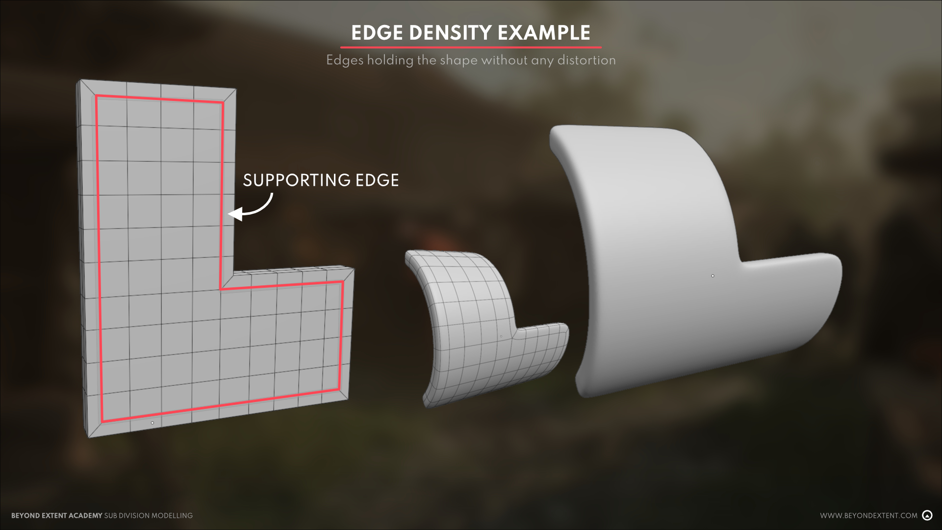
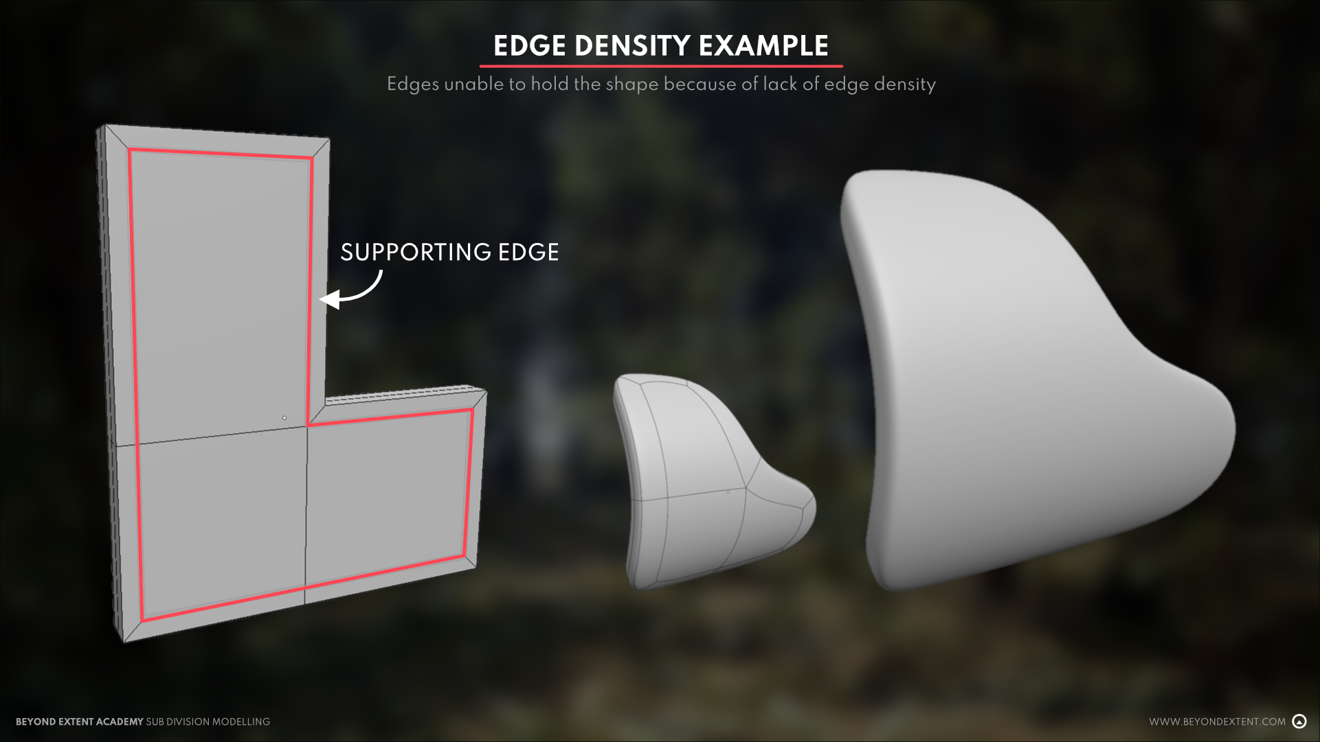
There are cases where these rules don’t need to be followed so strictly such as the middle sections of a plane or any unaltered surface. This is because the surface created where there are no alterations is simple and wouldn’t need as many edges to hold the shape.
EDGE FLOW
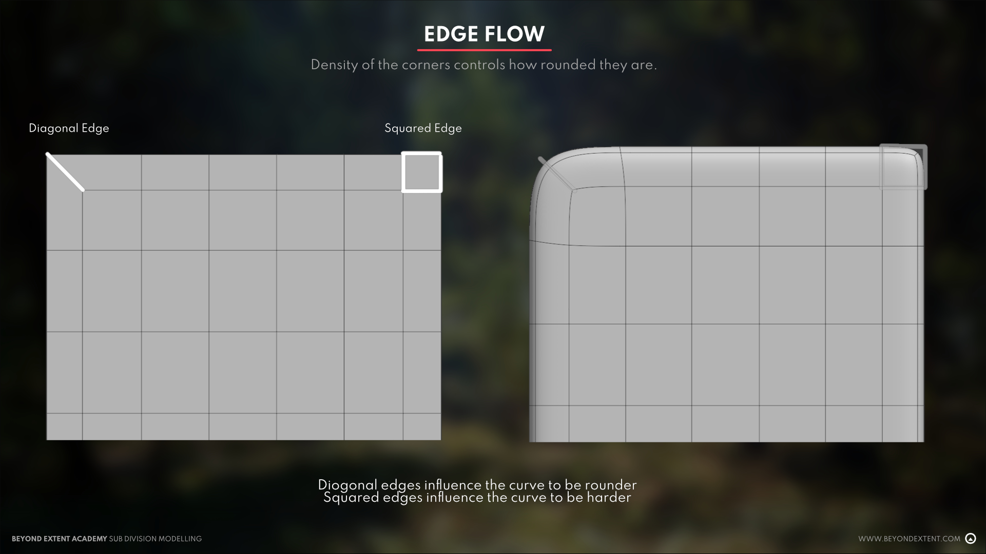
Edge flow, to put simply, is the way your edges flow along your model. As a beginner, you might not understand the influence edge flow has on your model, but by understanding these very basic principles, you can learn to manipulate and move your edges to get your desired subdivision result.
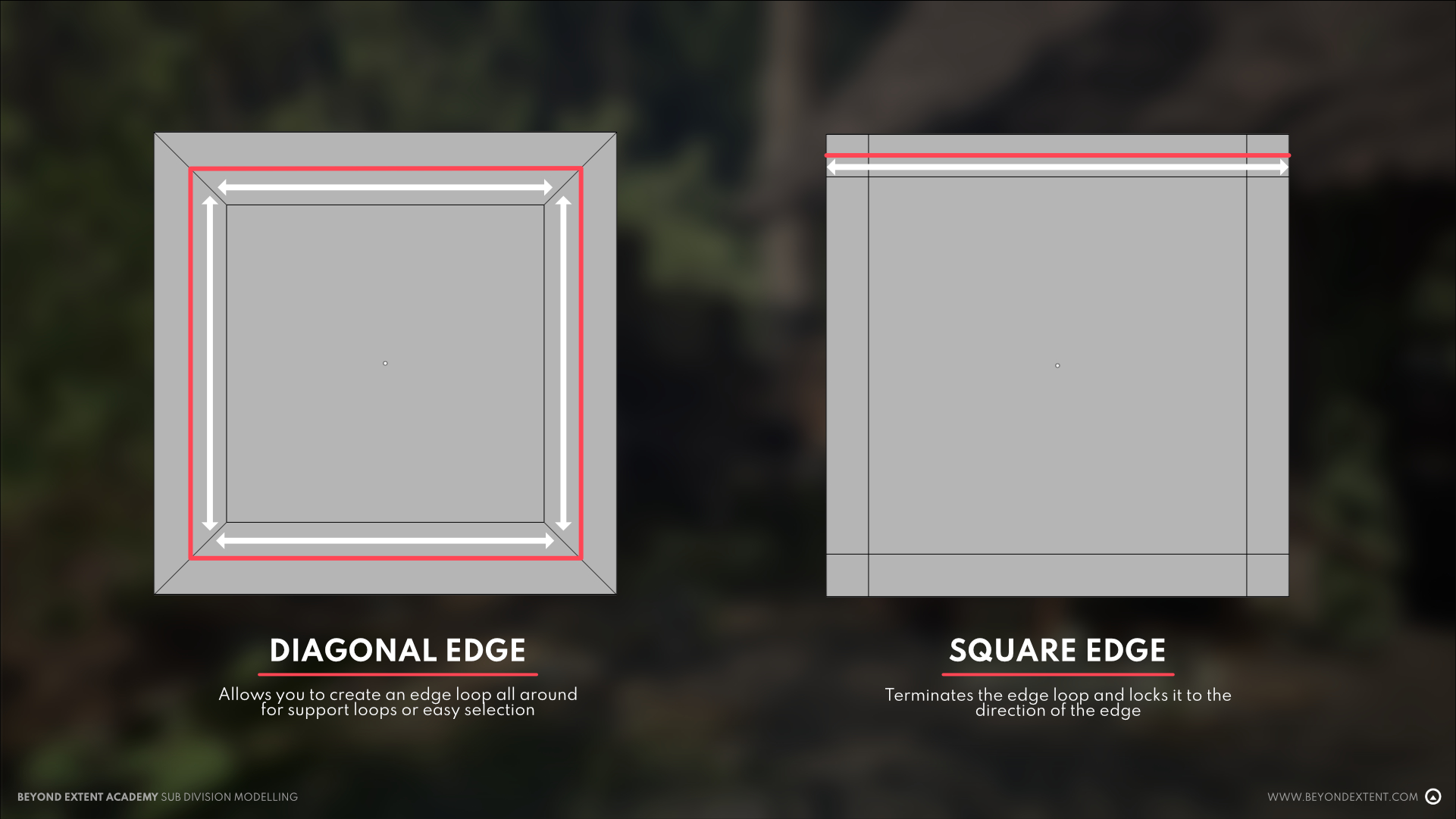
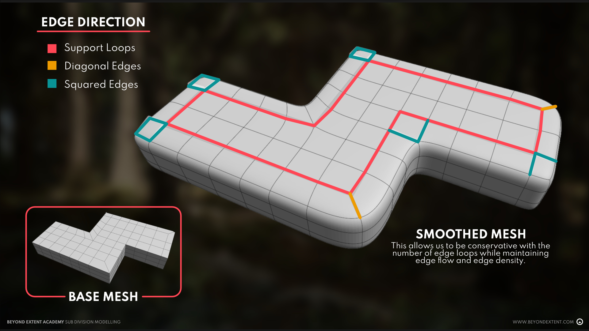
SQUARED EDGES
Squared Edges are a way to use edges to create a hard corner or hard edge along your model. This kind of support edge preserves the shape of the exterior outline of the model. This can also be controlled by the amount of distance the squared edges are from the main outline
DIAGONAL EDGES
Diagonal Edges on the other hand, are a way to use edges to promote softer and rounder curves. By using diagonal edges, you also allow yourself to maintain an edge loop all throughout the model.
EDGE REDIRECTION
Now that we understand these basics a little better, we can use all that we’ve learned in conjunction and learn something called edge redirection! Like the name states, it’s the act of redirecting your edges to achieve your desired result. Add squared edges in the form of support loops to create hard corners, and diagonals to create a steep curve.
3 POINT CORNER
You might also have noticed that the above image featured a different kind of corner than what we’ve tackled before, and it’s something often seen when we start redirecting edges to each other to maintain both edge density as well as edge flow. This kind of corner is created to serve as an in between of a square and diagonal edge without adding any more additional edge loops, essentially just reusing what we have.
It also allows the edge to be adjusted in a much more flexible way compared to just simply using a squared or diagonal edge.
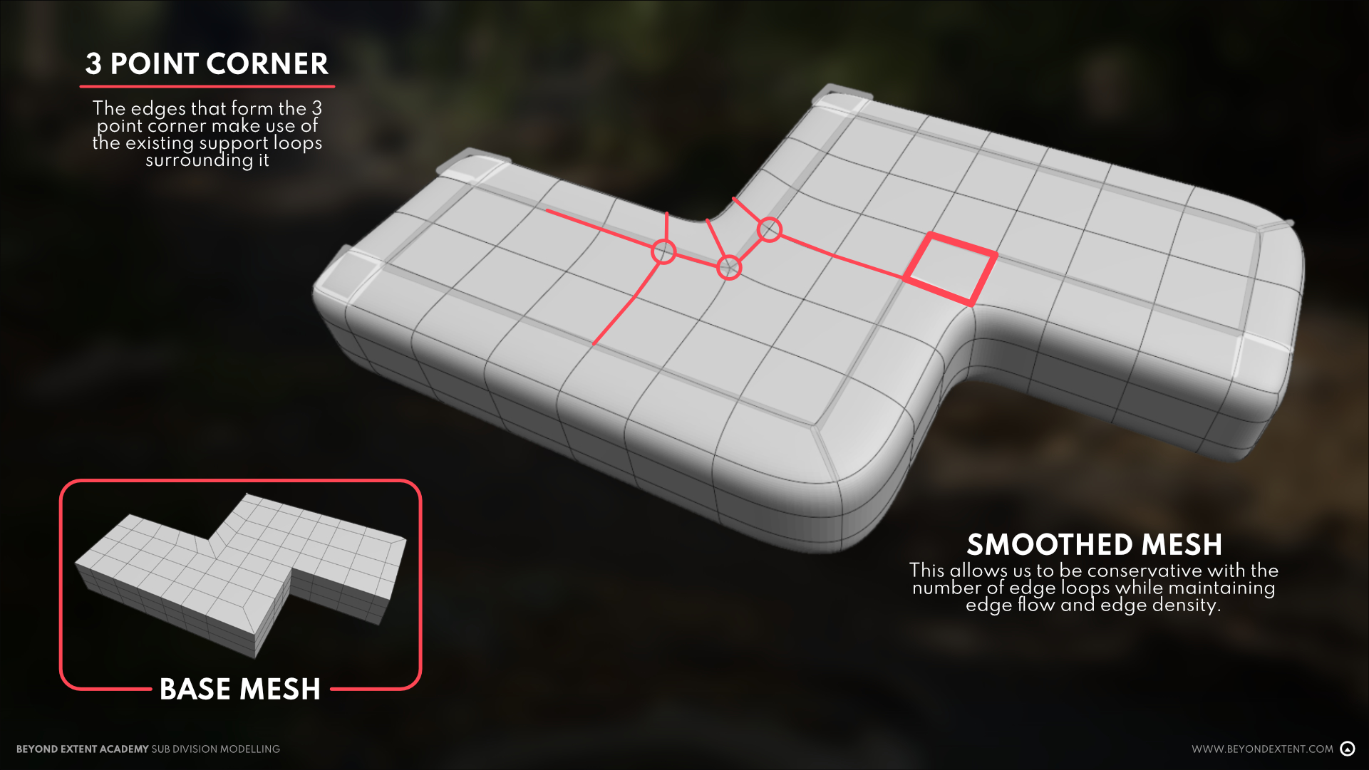
Do note that this kind of redirection was created by deleting or moving edges around. Simply adding loops without manually deleting and redirecting the edge does not grant you the 3 Point Corner. Analyze the edge flow and see what you can work with by utilizing the minimum amount of edges needed before adding more.
TERMINATING EDGES
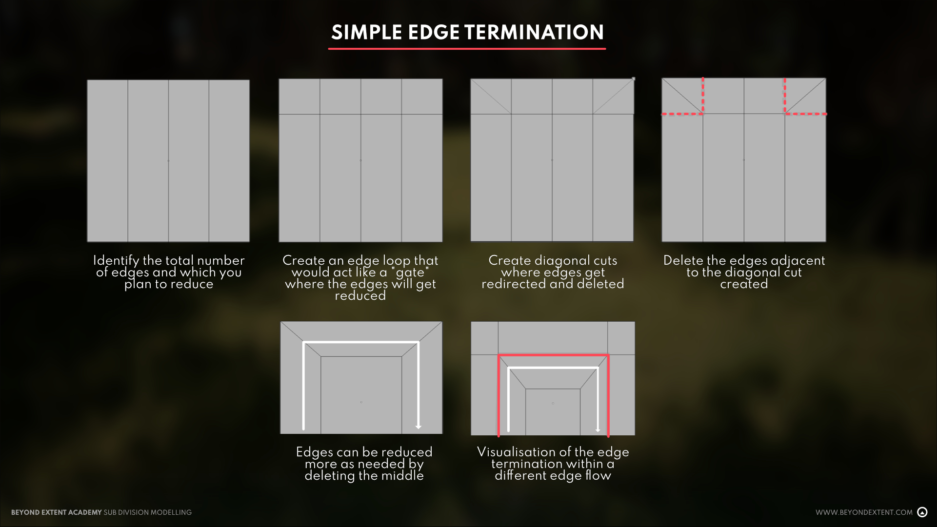
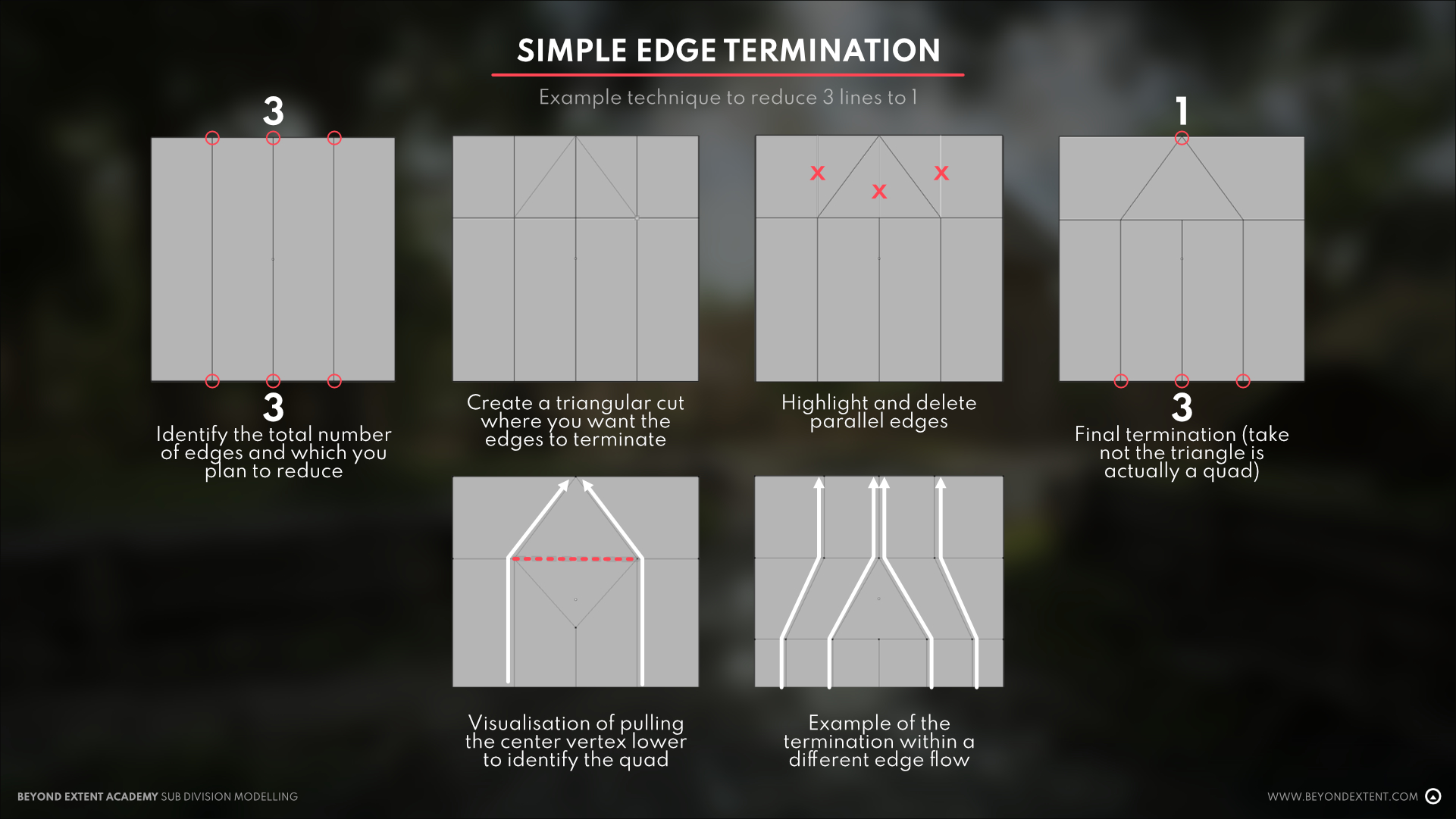
What is an edge termination? Basically, it’s a type of redirection where instead of allowing the edge loop to go across the whole model, you terminate and reduce it only to where it’s needed. We do this to align with edge density and keep everything across the model consistent. We don’t always need additional edges in certain places, so edge termination is a great way to do a little housekeeping with your edge flow.
<aside>🔥 (additional fun redirection and termination examples: 1, 2, 3)
</aside>
These are not the only ways to terminate edges though, and there are plenty more that exist depending on usage and edge density, but it’s important that we’re able to identify the ones that are simplest and practice our redirection and termination skills to create new ones that we might find useful for our models. At the end of this lesson, I will be including additional resources however for other edge termination examples.
At the end of the day, every person has their own workflow, and while the principles remain the same, it’s also beneficial that we develop a workflow that works for us and our needs. Remember these basics and you’ll be able to navigate around edges like a pro!
CYLINDERS
When working with cylinders, a good rule of thumb would be to use an edge count of anything divisible by 8. This provides enough edge information to work with that all edges terminate in the center to form perfect quads with an even amount of distribution across the whole circle.
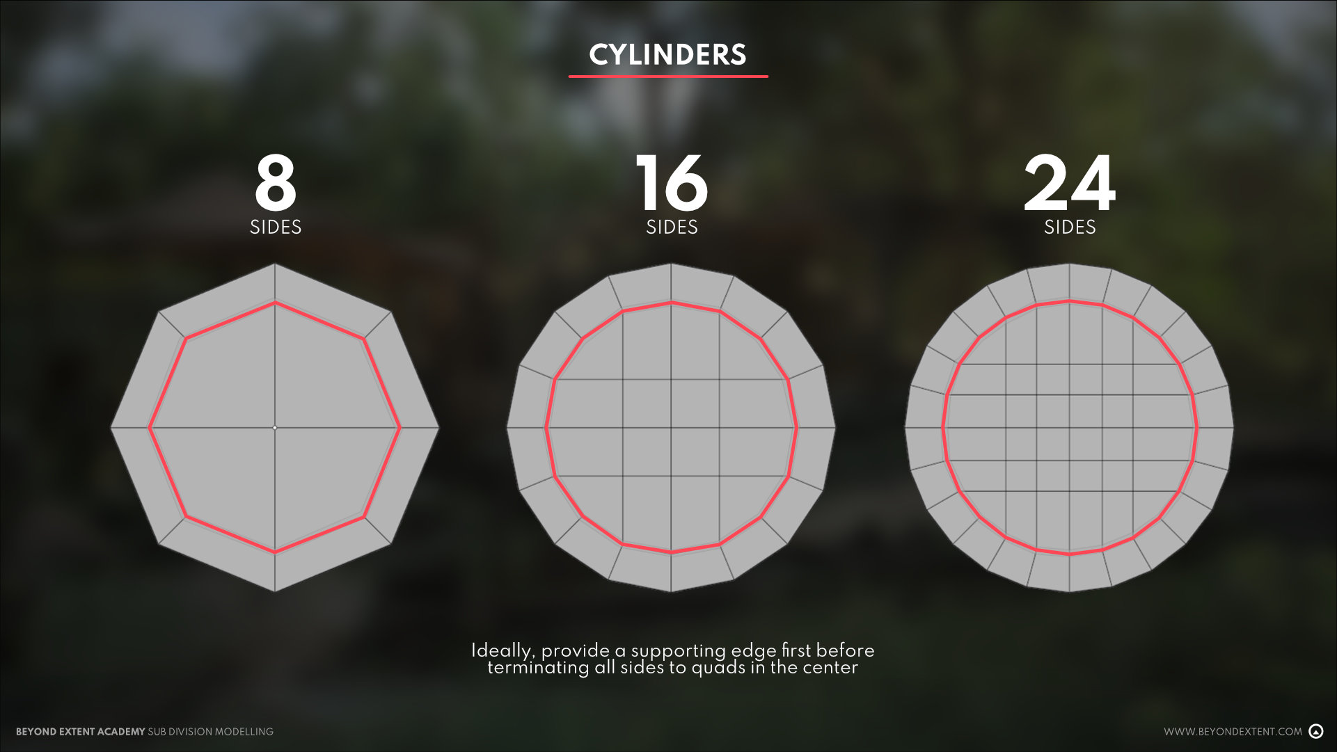
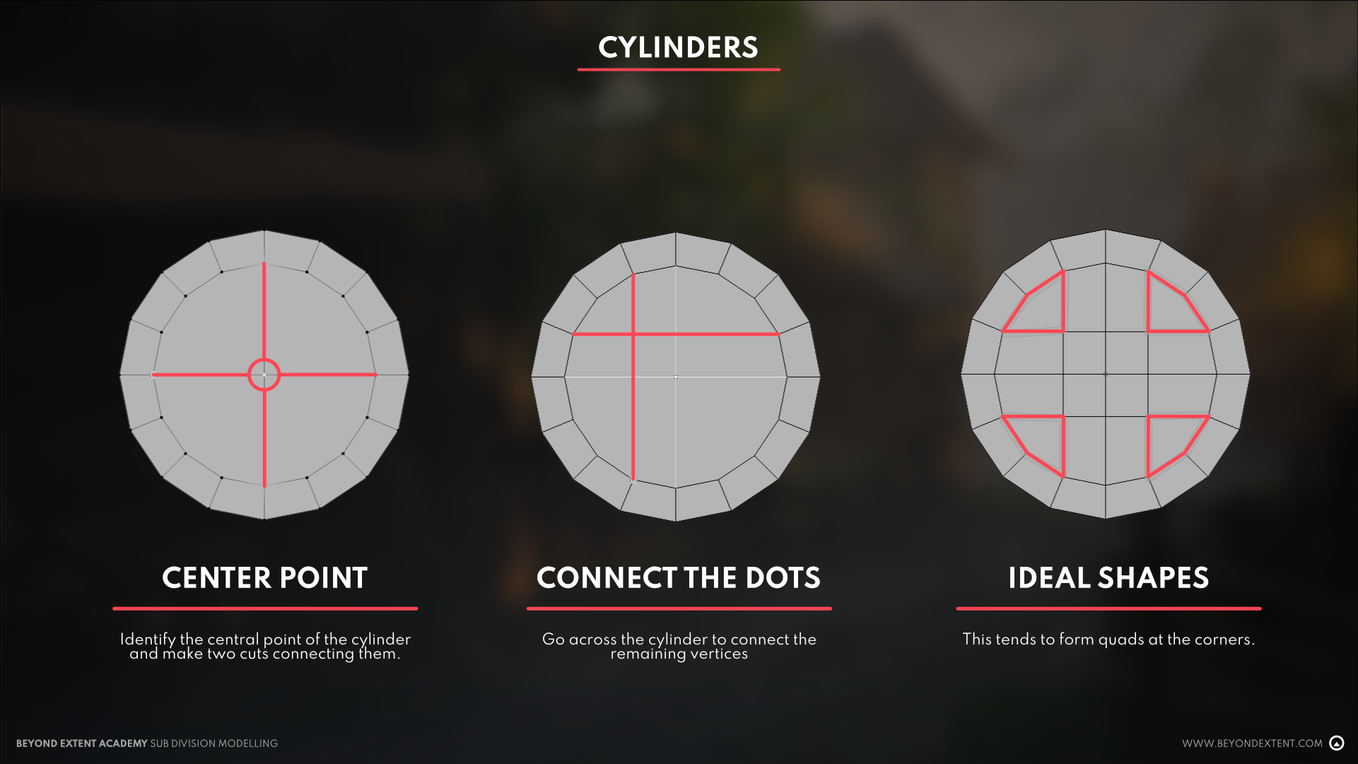
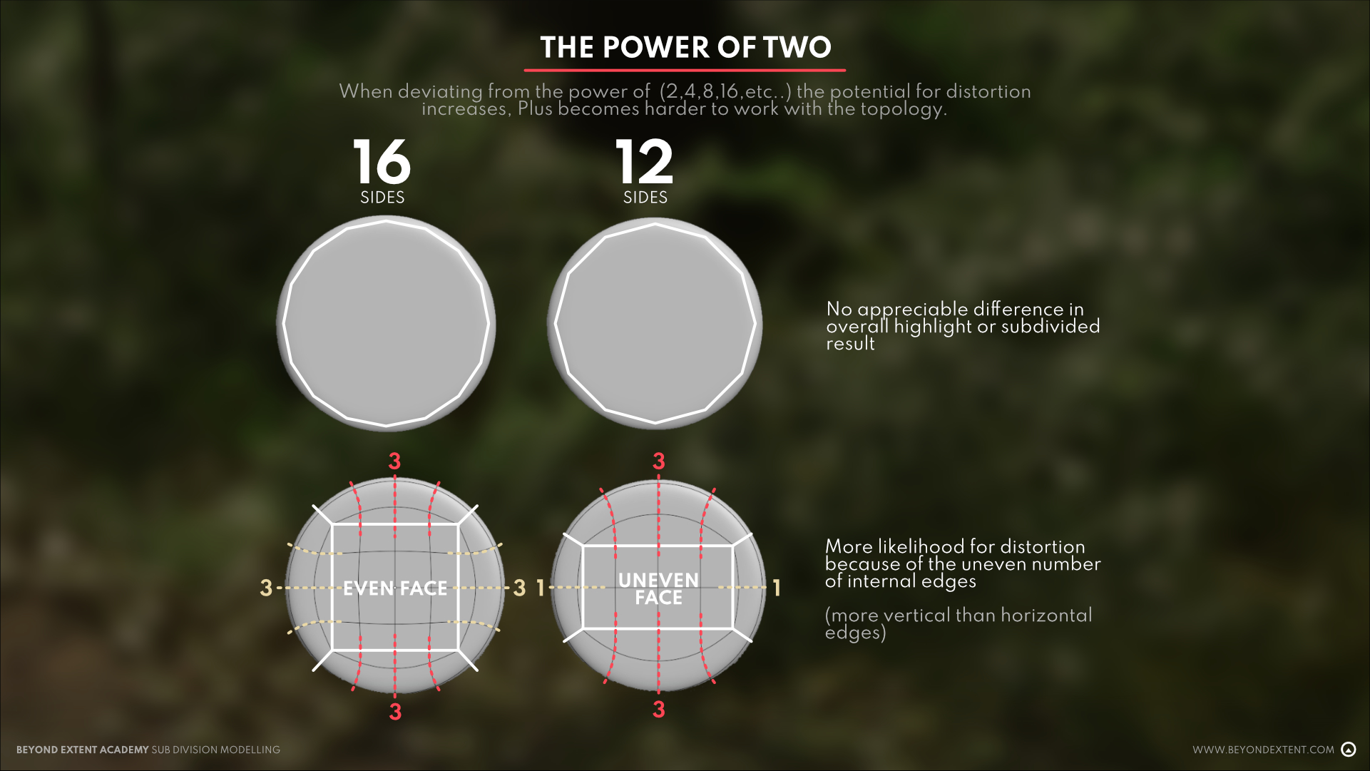
The reason we do this is to prevent any distortion across all sides of the cylinder when subdivided. However, this doesn’t mean that other numbered cylinders won’t work, just that this set of examples provides the most evenness across the board. This unevenness becomes more an issue down the line when merging cylinders with other cylinders or other irregular shapes because of the unequal edge distribution. This does not necessarily mean that they’re impossible to use but require some more effort to ensure that you get your desired result.
CYLINDER TO CYLINDER
When it comes to merging cylinders to cylinders, we must focus on aligning both the vertical and horizontal edge loops to ensure a smooth transition. This is where having the same number of edges across both objects matters as this influences the highlight created when merging these two shapes together.
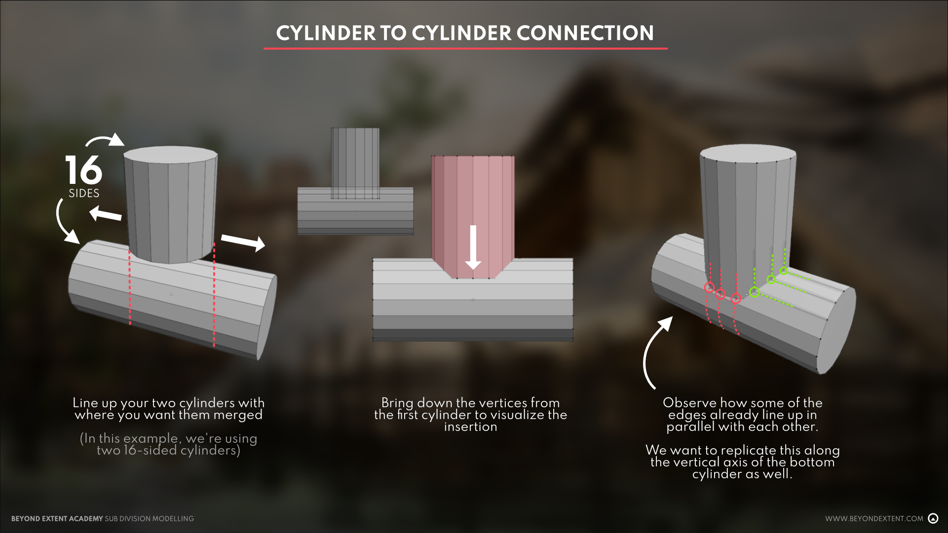
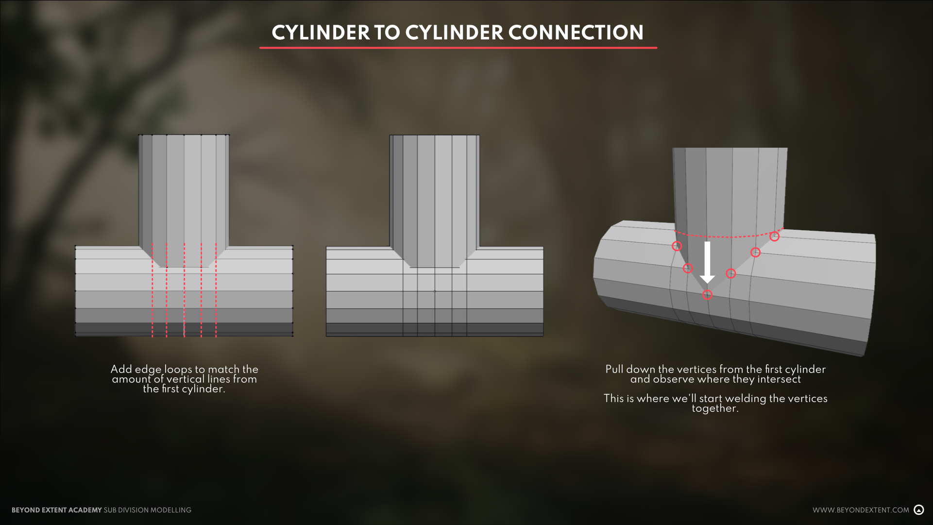
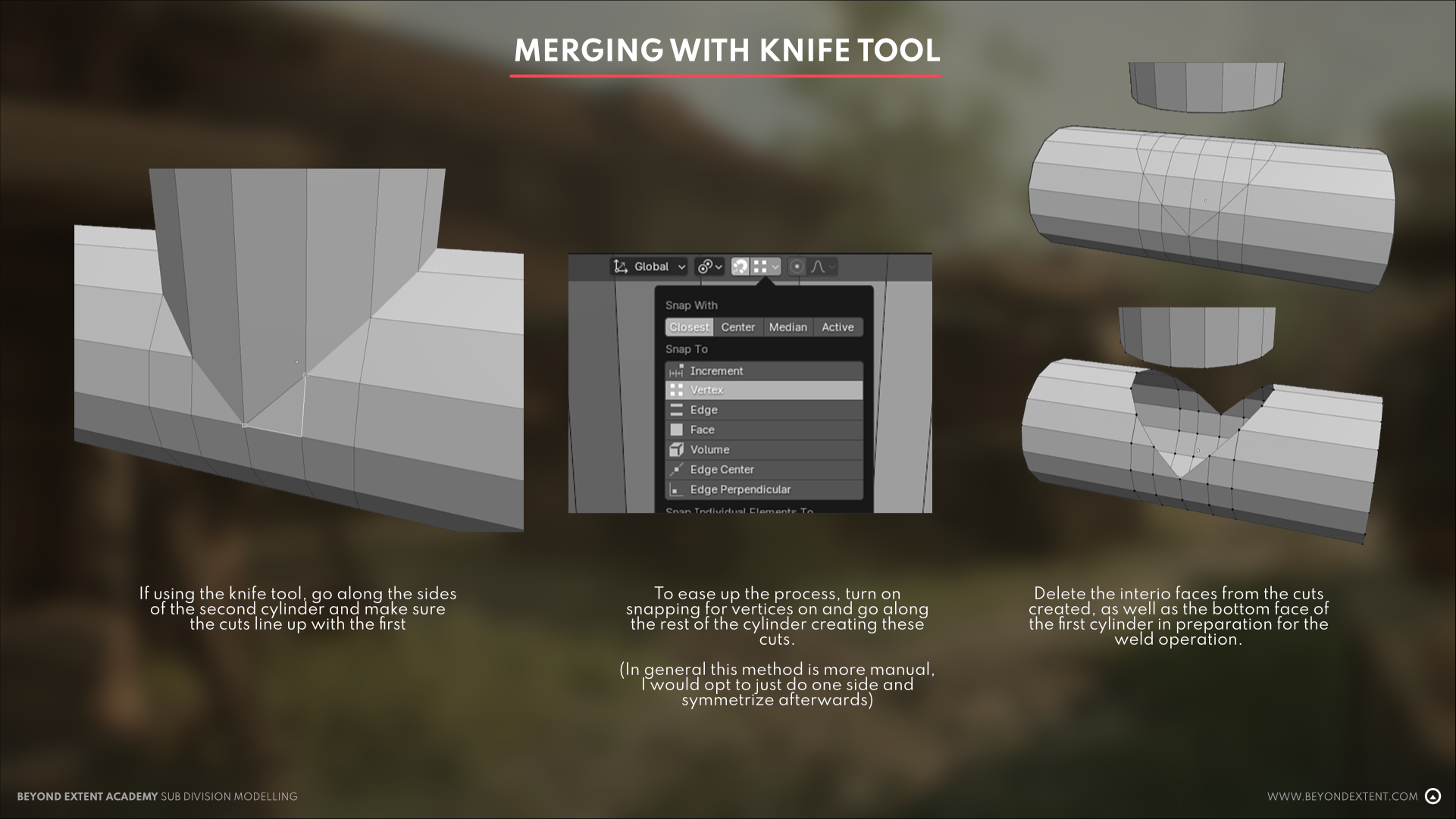
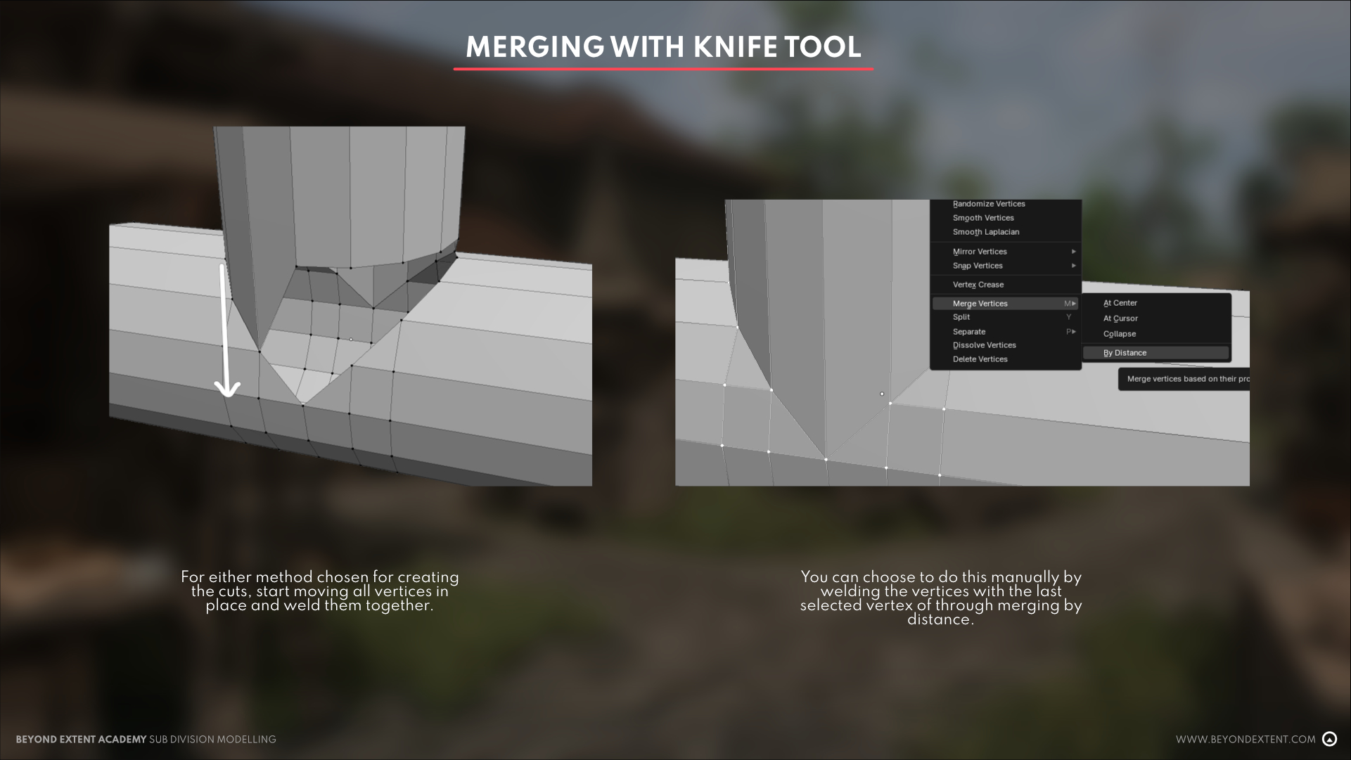
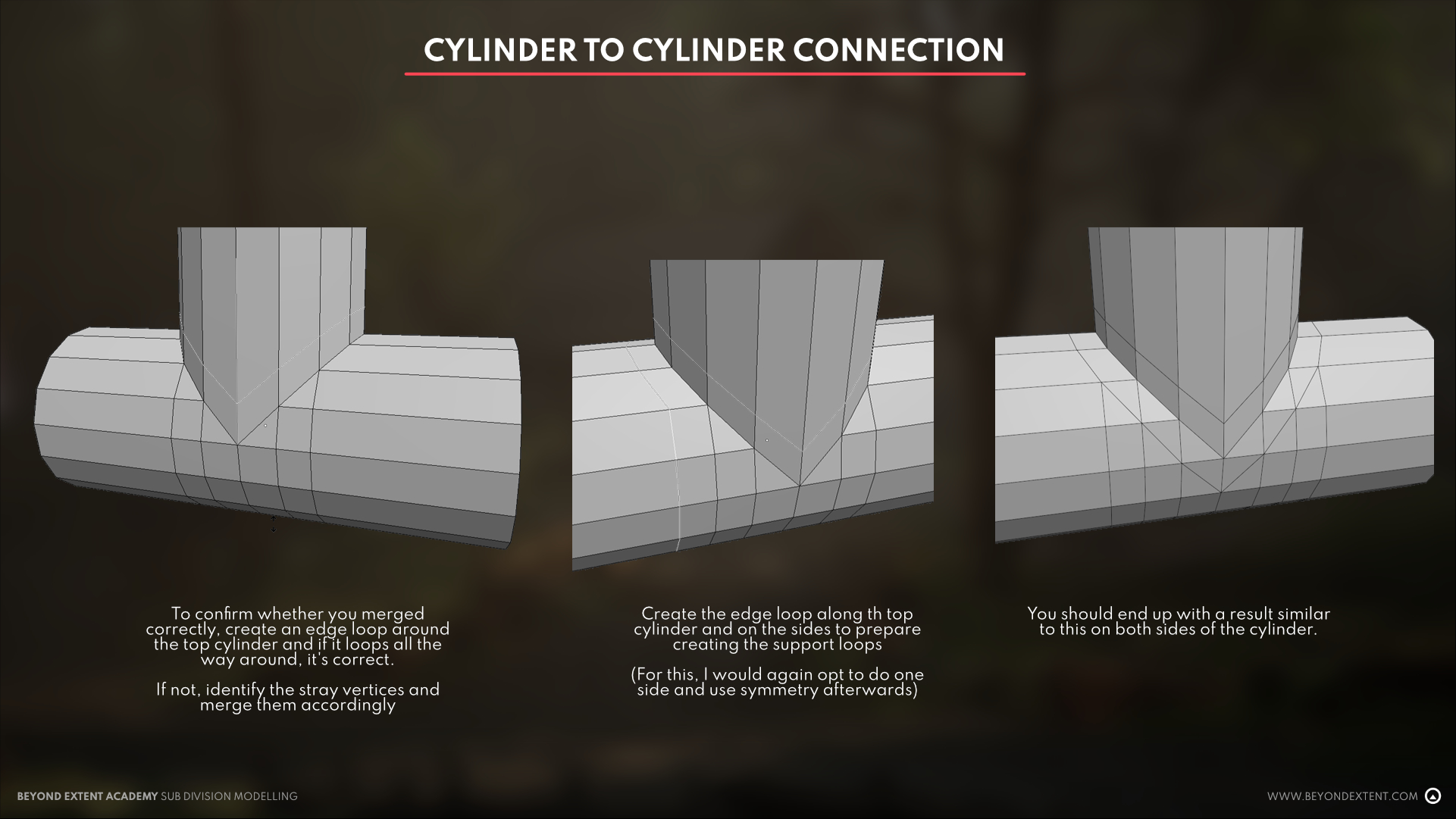
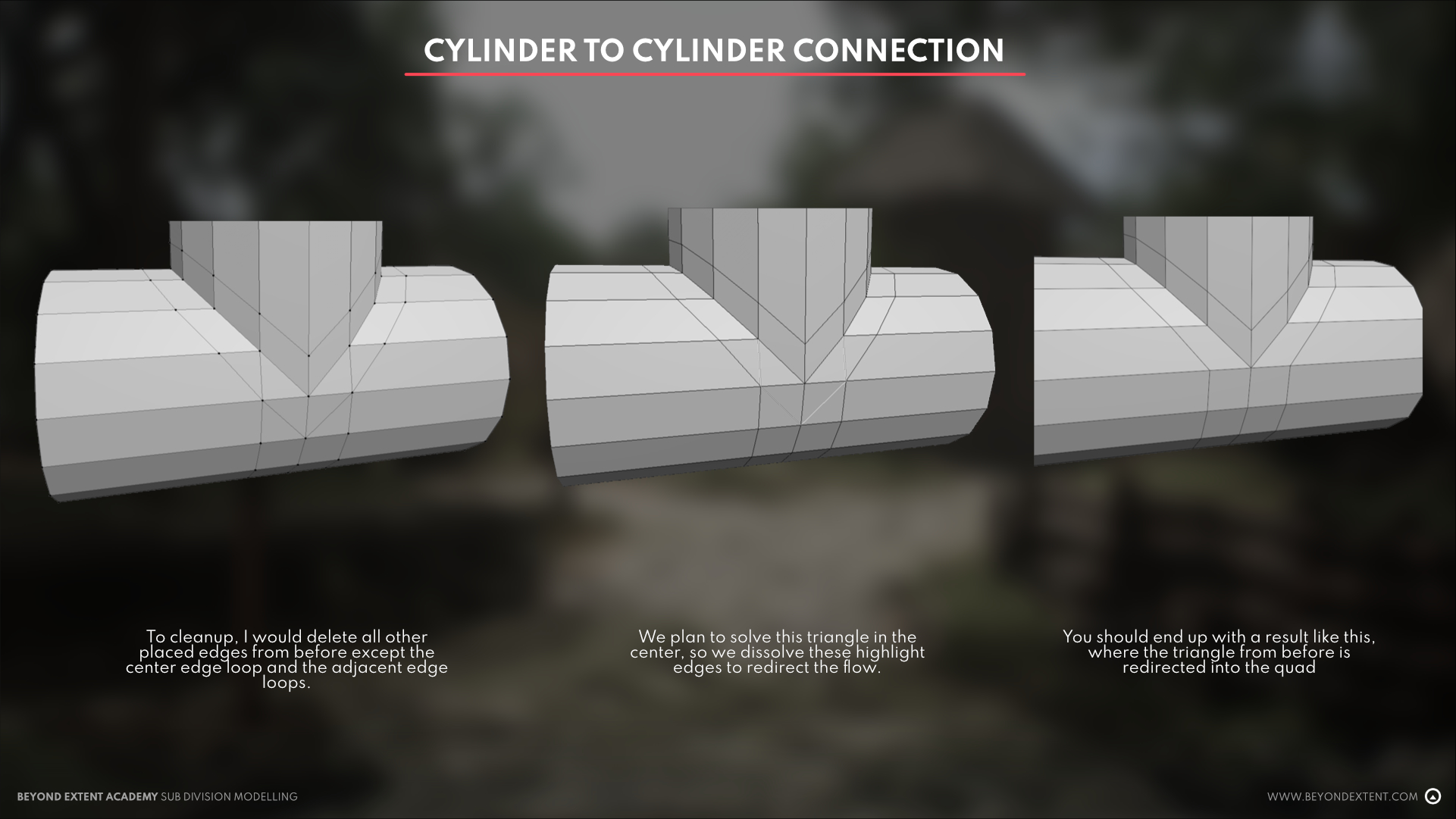
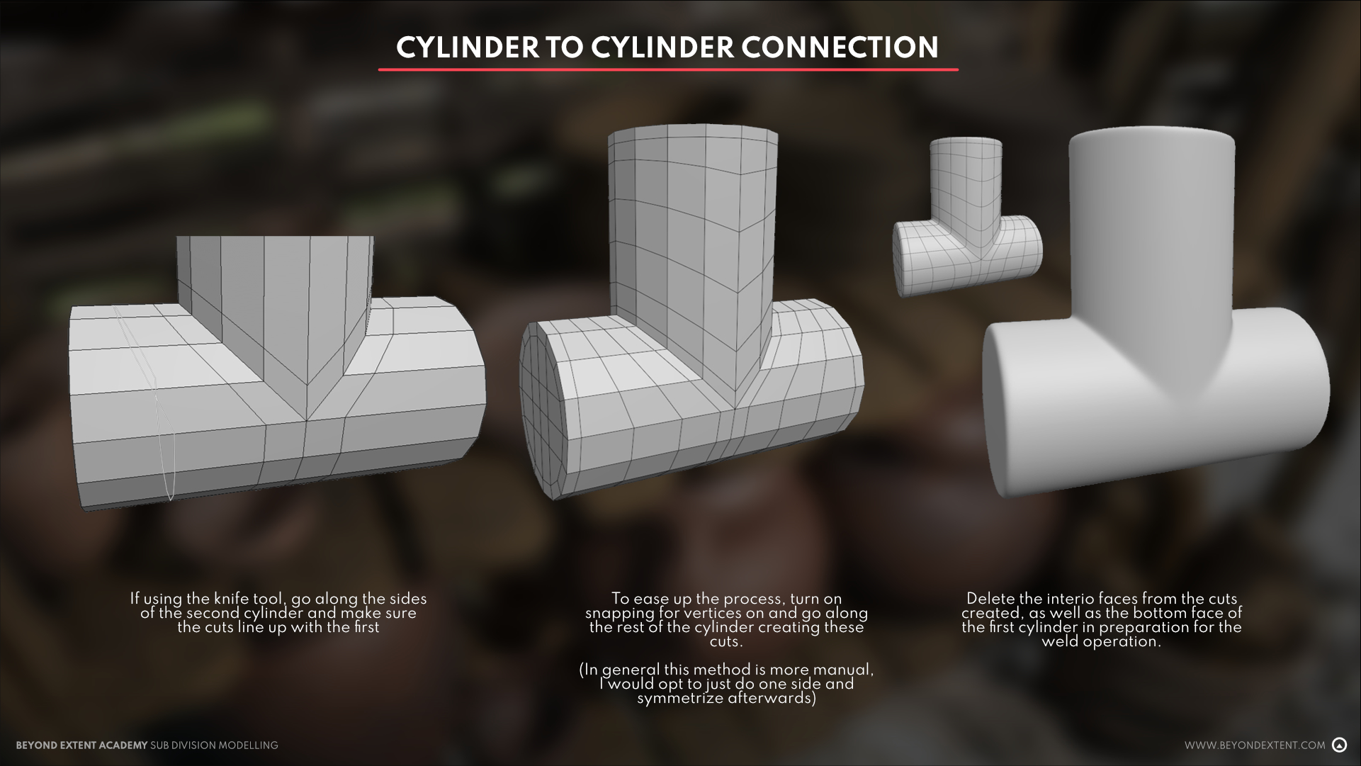
<aside>☝ Do note, cylinders and curved surfaces are more prone to distortion, so it’s generally recommended to not move the foundational edge loops around as this greatly influences the bounce light reflected off of the surface.
</aside>
<aside>💡 GENERAL REMINDERS:
- Start as low poly as you can! Create the overall shape of model first before adding in any supportive loops or additional edges
- Create duplicates of your base mesh before starting. This lets you go back to certain points of your model that you’re good and satisfied with instead of starting all over when things go bad.
- Support edges always follow the outline of the outermost edge. When in doubt, your outline determines the flow of your supportive edge
- Check subdivision preview often! Nothing hurts more than putting in a lot of effort then figuring out things don’t work.
- It doesn’t hurt to delete edges and redo them. Don’t be tied down by the work you’ve done if it’s not contributing to anything and is just making things difficult for you. Scale back, start small, and redo things. It will always be easier the next time around.
- Use a dark reflective material. For this tutorial, I used purple for ease of viewing but typically a dark colored Blinn or any dark reflective material works well. This is because distortion is easier to see this way as opposed to using a lighter and less reflective material.
- Practice practice practice! There is no one solution to subdivision. Who knows? You might come up with a technique that isn’t widely adopted but is useful and easy for you!
</aside>
“GOOD” AND “BAD” TOPOLOGY
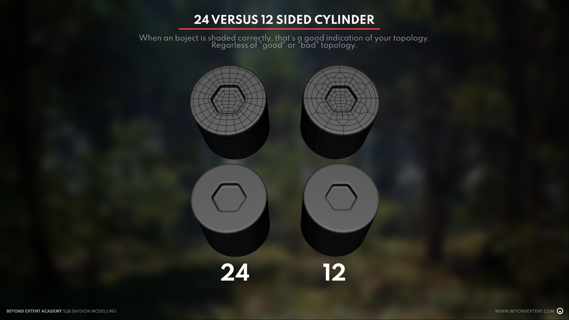
You’re likely wondering why I left this for the end, and I have a very good reason for it. A lot of the time, we find many examples online on “good” and “bad” topology, and it can be difficult for students to understand what essentially makes them good or bad. The primary answer I have for this would be context.
At face value, we cannot simply identify the difference just on wireframes alone. We have to understand what the context of the model is before we can make any real judgments on it, and even then, everyone has their own workflow and as long as it works for whatever you need it for, then it’s good! If it doesn’t and fails to do what’s intended, then that’s where we can call it bad and rework it until it’s better.
Here is an example below of a breakdown I had done over how to do a simple edge termination. One I did with more edges, the other with less, but with a slightly altered edge flow. The end result is the same because I understood how edge flow works, and I was able to utilize it correctly. Does it make the first example more incorrect because I added more edges? Or is the second incorrect because I added an additional step?
This is where context matters, and where the understanding of edge flow and edge redirection matters more than just simplifying something as “good” or “bad”. In reality, they are both fine! The standard rules can always be attacked differently, and it will encourage more experimentation through trial and error. Find the workflow that works for you but be critical of any kind of simplification on a complex topic as it might hinder your learning.
With regards to what “bad” topology might actually be, you can find them in things that have incorrect shading, inconsistent edge density, or strange “lumpiness” in things that were intended to be smooth. These are the cases where they would objectively be considered bad and would require fixing.
But what about NGons and Triangles? Is Quad only the only way?
Like with everything, not necessarily! Again, at the end of the day, if it looks good subdivided, then it isn’t incorrect; just different. Doing something quad only is a good reference point but shouldn’t be taken as gospel 100% of the time. As a student, I would recommend doing Quad only at the beginning to learn, and only incorporating NGons and Triangles once you’ve gotten a hang of how general topology and flow works.
The main reason Quads are great is because they are largely predictable and work well across both games and film. Film requires quads because of the nature of their work and how it makes things easier, meanwhile, with games, subdivision can be used as a step to make a mid-poly model for your highpoly or your final highpoly after applying subdivision. They are largely clean to work with and easy to understand especially when working in collaboration where other people may need to take on your work.
Tris can be used when when you require creating a pole, or a pinch in your topology. The pinches can range in how strong they look so just be careful where you put them!
Ngons can be the most temperamental and misunderstood because of the lack of defined clarity in them, where “N” is the designation of any number additional vertices. This makes working with them a bit trickier, but knowing how they can be used to leverage subdivision can be useful as after applying any subdivision, the program terminates them into quads anyway!
All of these are just a matter of knowing how topology and subdivision work with each other. There are known rules but being able to leverage and break them is a great way to learn new and different techniques!


